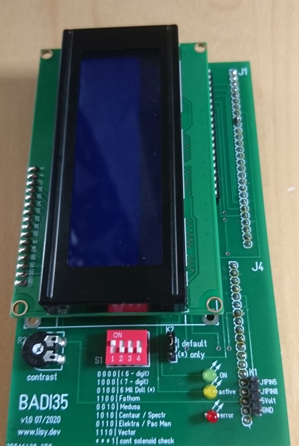
Bally LCD display
The intention is to have something to test display output on the bench without the need for high voltage, just 5 Volt is needed. If you are using the PCB with LISY35 it will fit on J1 and J4, with a Bally MPU it fits on J1 only, you need to spend two extra wires (5 Volt & GND) from J4.
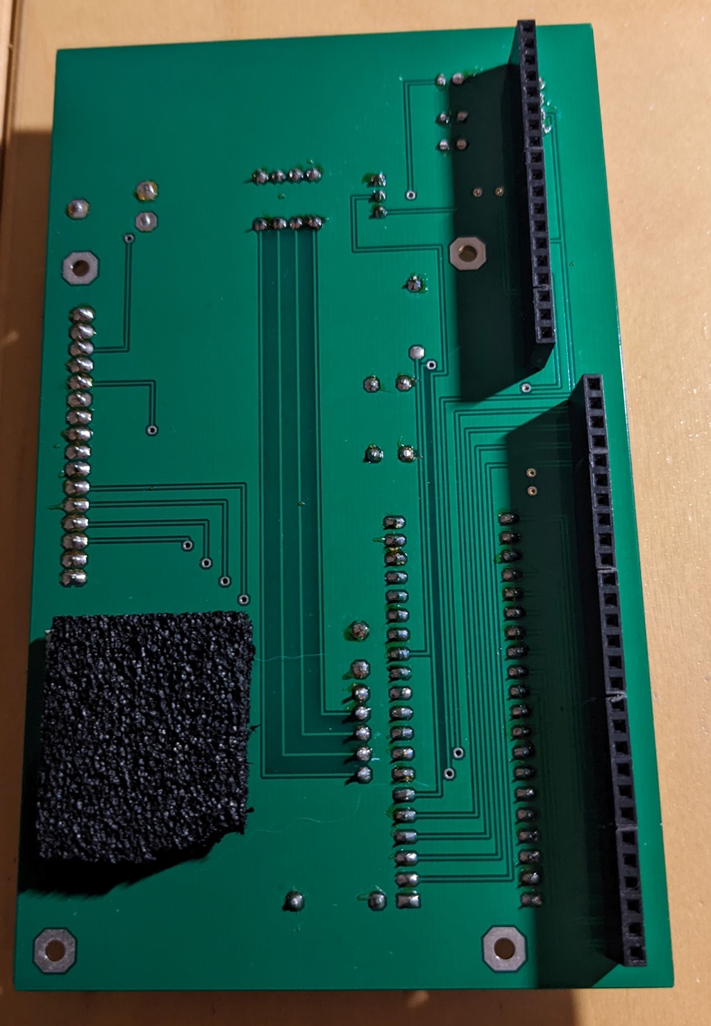 female connectors on the back
Note: with hardware version 1.0 you need to solder a bridge between pins 9 and 10 of J1!
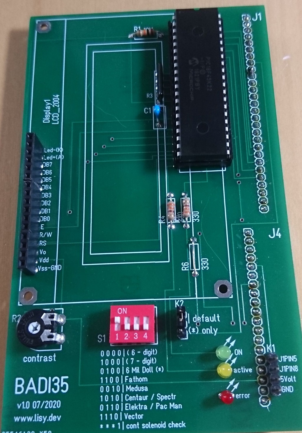
For the 4x20 LCD display you can use the one from the 'Reichelt shop cart' or any other HD44780 compatible display ( LCD display on Aliexpress )
Documentation
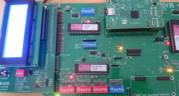
BADI35 can work with all Bally & Stern Games manufactured from 1977 to 1985 by selecting the DIP switches on S1. You just need to select if your game has 6- or 7-digit displays.In addition some 'special' games need to be selected seperatly ( see comments on the PCB). In addition for '6 Million Dollar Men' the jumper 'K2' need to be set to '*' instead of the postion marked as 'default'.
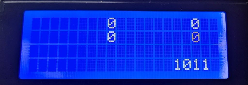
By setting DIP4 of S1 to ON Badi35 will show the status of the four 'continous solenoids' in the last line of the display.
The connectors J1 and J4 on BADI35 are the same as on Bally/Stern MPUs. There are small differences in handling if you use BADI35 with my LISY35/BallyFA or with the original MPU (see below).
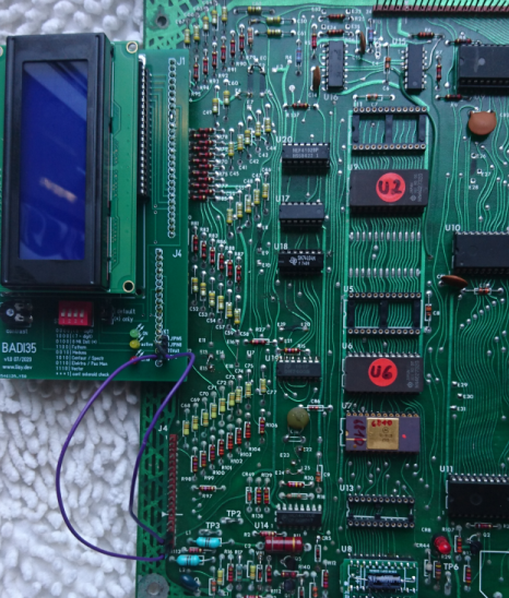 BADI35 with a Bally MPU
On an original MPU place J1 of BADI35 at J1 on the MPU.
In addition you need to wire the connector K1!
K1-Pin4 (GND) -> J4-Pin18 or 19 (bottom) or use TP4 (GND)
K1-Pin3 (5Volt) -> J4-Pin16 or 17 or use TP5 (5V)
K1-Pin2 (J4Pin8) -> J4-Pin8 ( not needed for 6-digit games)
K1-Pin1 (J4Pin5) -> J4-Pin5 ( not needed for 6-digit games)