Bally LED anti flicker solution
When using LEDs instead of standard Bulbs within Bally pinballs, the LEDs are known to 'flicker'. The usual solution to that is to solder an additional resistor to each LED or use special LEDs which do have this resistor included.
This solution is using a cheap PIC (which need to be programmed with the 'hex' file provided)
In case you do not have a PIC programmer I do recommend a PICKIT3.
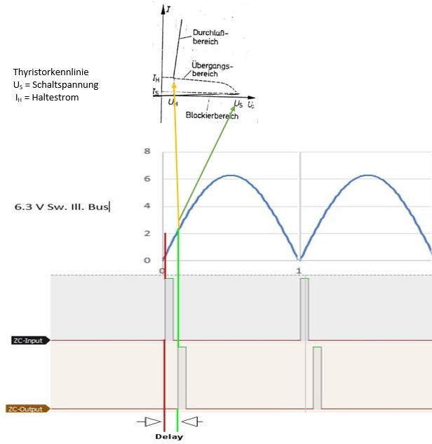
The PIC do modify the timing of the Lampdrivers by delaying the Zero Cross signal. For those who are interested you find a detailed description at the end of this page.
Note: when using my LISY35 or BallyFA replacement MPUs this solution is already included.
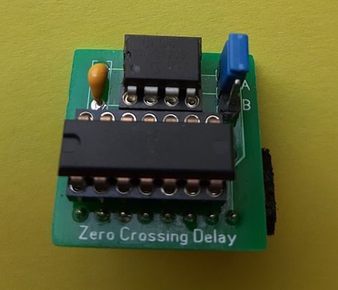
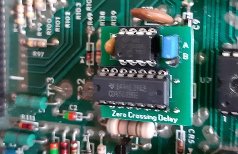
The anti flicker module will be placed at the original location of 'U14'
Set the jumper to position 'A' to activate the Module. With position 'B' the module is deactivated, in case you do not want to use LEDs anymore. (normal bulbs will be slightly darker with an activated modul).
In addition to the PCB you need the (programmed) PIC (PIC12F1612 or PIC12F683), two adapter strips, a 100nF Kerko and an IC socket.
You need to desolder U14 (4049B) and replace it with an IC socket. The anti flicker module will be placed as 'piggy back' PCB in this socket and will reuse the original U14.
Different Modules are available for Bally, Stern and Alltek MPU.
mod for games with solenoid expander boards
On games with solenoid expander boards you need to add a small mod on the expander PCB in order to have it work together with my anti flicker module!
modification needed: additional 47uF/25V capacitor plus 1N4148 diode.


