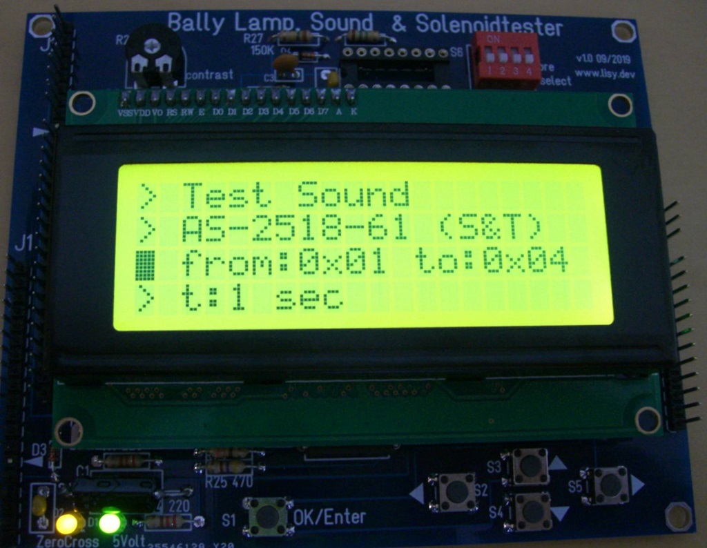
Bally Lamp, Sound & Solenoidtester
With a PIC and a Display with 4 lines / 20 characters
Code based on the LISY35 PIC code
Documentation
The Bally tester PCB comes with 3 connectors (J1, J2, J3) which are pin compatible to the connectors available on the original MPU. Connection of J1 is needed as a minimum as the tester is powered via J1 pin 16&17 (5Volt) and J1 pin 18&19 (GND). Connection of J2 and J3 are optional, depending of the things you want to test.
overview:
J1 (Equivalent to J4 on MPU): 5Volt power supply of tester PCB; test Sound & Solenoids; test zero cross signal (LED on PCB)
J2 (Equivalent to J1 on MPU): test lamps
J3 (Equivalent to J3 on MPU): only needed if you want to start/stop the current test from
'outside' the cabinet with the credit button of the pinball (same function as OK/Enter button
on the PCB)
The 4 switches in S6 “Pre-Select” are for future use and have no function with the current software version.
For the 4x20 LCD display you can use the one from the 'Reichelt shop cart' or any other HD44780 compatible display ( LCD display on Aliexpress )
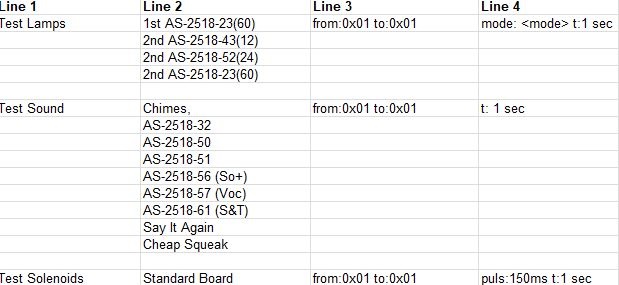 available Options in menu
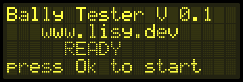
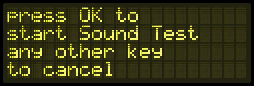
press OK switch to start
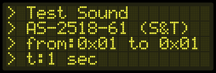
select Options by pushing left/right arrow within line 1 & 2
select numbers by pushing right arrow, adjust numbers with up/down arrow, confirm numbers by Pressing OK
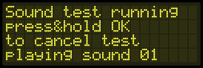
test starts by pressing OK switch ( Cursor in Position 1, line 1-4 )