WillFA11 FPGA checker
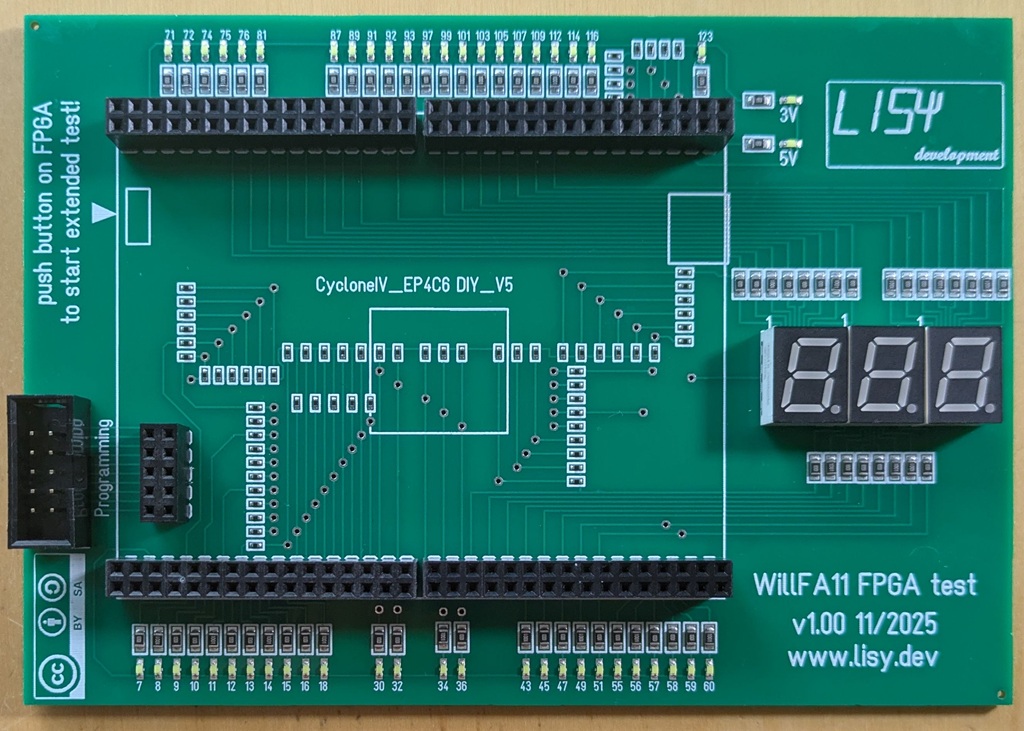
My WillFA11 CPU replacement for Williams SYS11C and Data East games comes with a self designed FPGA board which is different from my standard FPGA boards. With this testboard you can check all IO ports.
documentation
At start the 3digit LED display show the software version for a few seconds. Then the LED display and the upper and lower LEDs are switched ON/OFF in sequence.
This is 'Check 1' of the 72 output pins.
By pushing the switch on the FPGA you can step to the other tests:
Check 2: The LEDS at the lower row (26 output IOs) are switched ON/OFF on after another.
Check 3: The LEDS at the upper row (22 output IOs) are switched ON/OFF on after another.
Check 4: The LEDS in the LED display (24 output IOs) are switched ON/OFF on after another.
These IOs are needed for the 'extended' test routine. Checks 1 to 4 are manual tests, Watch carefully that all LEDs are working. The coresponding Pins for upper and lower LEDs is written on the PCB (see also picture above). For ports assigned to the LED display see table below.
Check 5 do test the 36 input IOs, this is an automatic test. Each failed IO port number is shown on the LED display and the test is paused. By pushing the switch again the test continous.
If all tests are succesfull (all input prots are working) the display will show 'PAS'.
In case there was an error the display will show 'Err'
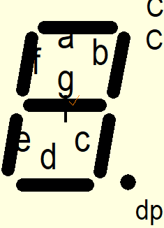
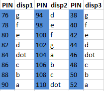
display segment pin assigments
all output